Overview
โปรเจกต์นี้เป็นการสร้างกล้องที่หมุนตามการเคลื่อนไหวของวัตถุ (Motion Following Camera Base) โดยใช้ Arduino เป็นหัวใจของระบบ รวมกับ Motion Sensor เพื่อตรวจจับการเคลื่อนไหว และมอเตอร์เพื่อหมุนแท่นกล้อง คำพูดหลักคือ "กล้องจะหมุนไปไหน ลูกศรการเคลื่อนไหวก็จะไป"
สาระสำคัญ: ระบบอัตโนมัติที่ใช้ Infrared Sensor ตรวจจับการเคลื่อนไหว แล้วส่งคำสั่งให้มอเตอร์หมุนแท่นกล้องให้เข้าเป้า สมบูรณ์แบบสำหรับการ Live Stream, สตูดิโอ หรือการเฝ้าระวัง
ผลลัพธ์ที่ได้คือ "Smart Camera Base" ที่สามารถจับตามการเคลื่อนไหวอื่น ๆ ด้วยเองโดยไม่ต้องมนุษย์ควบคุมด้วยมือ ยิ่งเหมาะสำหรับการสตรีมวิดีโอ (Streaming), สตูดิโอถ่ายภาพ, หรือระบบรักษาความปลอดภัย
See It in Action
ดูวิดีโอของการทำงานของ Motion Following Camera Base - กล้องจะหมุนตามการเคลื่อนไหวโดยอัตโนมัติ
Things You'll Need
เพื่อสร้างโปรเจกต์นี้ คุณต้องเตรียมอุปกรณ์และวัสดุดังต่อไปนี้:
-
Arduino Uno - ไมโครคอนโทรลเลอร์หลักของโปรเจกต์
-
Infrared Motion Sensor (PIR) - ตรวจจับการเคลื่อนไหวของคน/วัตถุ
-
2x DC Motor (3-6V) - มอเตอร์หมุนแท่นกล้องแนวราบและแนวตั้ง
-
Motor Driver Module (L298N) - ควบคุมการหมุนของมอเตอร์
-
Jumper Wires - สายเชื่อมต่ออุปกรณ์
-
9V Battery + Battery Holder - แหล่งจ่ายพลังงาน
-
USB Cable (Type A to B) - อัปโหลดโค้ดไปยัง Arduino
-
Servo Motor (optional) - หากต้องการความแม่นยำสูง
-
Wood/PVC Pipe - โครงสร้างแท่นกล้อง
-
Camera Mount Bracket - ที่ยึดกล้อง (1/4" screw standard)
-
Resistors & Capacitors - อุปกรณ์เสริมเพื่อเสถียรภาพวงจร
-
Solder & Solder Iron - เพื่อบัดกรี (ถ้าต้องการ permanent connection)
เคล็ดลับ: ถ้าเป็นครั้งแรก ลองใช้ Breadboard แทนการบัดกรี เพื่อให้แก้ไขได้ง่าย ต้นทุนประมาณ 1,500-2,500 บาท
The Story
โปรเจกต์นี้เกิดมาจากไอเดียง่าย ๆ ของคนที่ชอบทำ Live Stream บน YouTube หรือ TikTok แต่หนึ่งคนต้องจับกล้องตลอดเวลา ทำให้จำกัดมาก ถ้ากล้องสามารถหมุนตามตัวอัตโนมัติได้ ก็จะเป็นอิสระมากขึ้น
นี่คือจุดเริ่มต้นของ "Smart Camera Rig" - ระบบกล้องอัตโนมัติ ที่ใช้ Arduino + PIR Sensor เพื่อตรวจจับการเคลื่อนไหว แล้วให้มอเตอร์หมุนแท่นกล้องตามเป้า ผลลัพธ์คือการสตรีมวิดีโอที่ดูขนาดใหญ่และมืออาชีพ โดยใช้คนแค่คนเดียว
สถานการณ์จริง:
- Content Creator ขาด Budget สำหรับกล้องที่เคลื่อนไหวได้ (gimbal ราคา 10,000+ บาท)
- ต้องการให้กล้องติดตามตัวเอง พอเดิน ก็ตามโดยอัตโนมัติ
- วิธีแก้: สร้างมันเอง ใช้ Arduino + Motion Sensor ต้นทุน 1,500-2,500 บาท
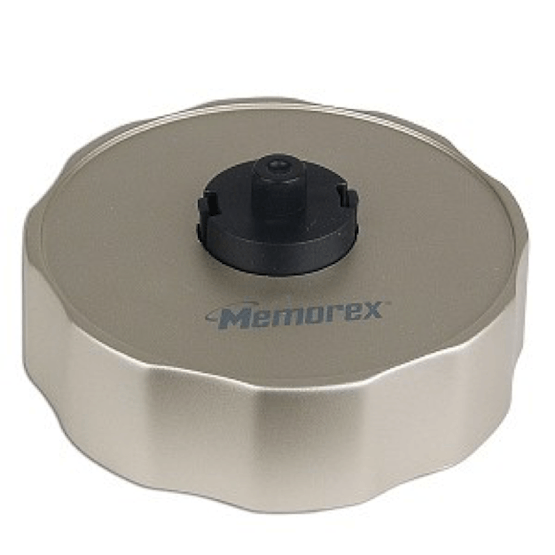
แรงบันดาลใจจาก CD Labeler - ทำให้เกิดไอเดียระบบหมุน
How It Works
ขั้นตอนการทำงานของระบบแบ่งออกเป็น 3 ส่วนหลัก:
ขั้นตอนที่ 1: ตรวจจับ (Detection)
PIR Sensor ตรวจจับการเคลื่อนไหวของคนหรือวัตถุ ถ้ามีการเคลื่อนไหว Sensor จะส่งสัญญาณ HIGH ไปยัง Arduino
ขั้นตอนที่ 2: ประมวลผล (Processing)
Arduino รับสัญญาณจาก Sensor แล้วคำนวณทิศทาง ระบบใช้ 2 มอเตอร์ - มอเตอร์แนวราบ (Pan) และมอเตอร์แนวตั้ง (Tilt) เพื่อหมุนแท่นกล้องให้เข้าเป้า
ขั้นตอนที่ 3: หมุน (Action)
Motor Driver รับคำสั่งจาก Arduino และป้อนพลังงานให้มอเตอร์ แท่นกล้องจะหมุนตามที่คำนวณไว้ จนกว่าจะเข้าเป้า
ทั้ง 3 ขั้นตอนนี้เกิดขึ้นต่อเนื่องอยู่ตลอดเวลา ทำให้กล้องสามารถติดตามการเคลื่อนไหวได้อย่างเรียบลื่น
Wiring
การเชื่อมต่อวงจร (Wiring) เป็นส่วนสำคัญที่สุด ต้องเชื่อมต่ออุปกรณ์ให้ถูกต้อง มิฉะนั้นโปรเจกต์จะไม่ทำงาน
Arduino to Motor Driver (L298N):
Arduino Pin 8 → Motor Driver IN1
Arduino Pin 9 → Motor Driver IN2
Arduino Pin 10 → Motor Driver IN3
Arduino Pin 11 → Motor Driver IN4
Arduino GND → Motor Driver GND
Arduino to PIR Sensor:
Arduino Pin 2 → PIR Sensor Signal
Arduino 5V → PIR Sensor VCC
Arduino GND → PIR Sensor GND
Motor Driver to DC Motors:
Motor Driver OUT1/OUT2 → DC Motor 1 (Pan/Horizontal)
Motor Driver OUT3/OUT4 → DC Motor 2 (Tilt/Vertical)
Power Supply:
9V Battery → Motor Driver +12V/GND
USB Power (Arduino) → Arduino USB / or 9V to VIN
เคล็ดลับ: ใช้ Breadboard ขนาดใหญ่ (830 pins) ในตอนแรก เพื่อให้หา Bug ได้ง่าย
Construction
ขั้นตอนการสร้างแท่นกล้องไม่ยากมากนัก หากคุณมีเครื่องมือพื้นฐาน:
-
สร้างโครงสร้างแท่นกล้อง
- ใช้ PVC Pipe หรือไม้ไอ้ขนาด 2-3 นิ้ว สร้างแท่นฐาน (Base)
- เพิ่มแกนหมุนแนวราบ (Horizontal Axis) เพื่อหมุนไป-มา
- เพิ่มแกนหมุนแนวตั้ง (Vertical Axis) เพื่อหมุนขึ้น-ลง
- ยึด Camera Mount Bracket ที่ปลายสุด
-
ยึดมอเตอร์
- ยึด DC Motor 1 ให้หมุนแกนแนวราบ (ใช้ Gear หรือ Belt)
- ยึด DC Motor 2 ให้หมุนแกนแนวตั้ง
- ใช้ Metal Bracket หรือ L-bracket สำหรับการยึด
-
ติดตั้ง PIR Sensor
- ติด PIR Sensor ที่ด้านหน้าของแท่นกล้อง หรือด้านข้าง
- ตั้ง Detection Range ที่ประมาณ 2-3 เมตร
- เชื่อมต่อสายไปยัง Arduino
-
ทำการ Wiring
- ติด Breadboard บนแท่นกล้อง หรือ ภายนอก
- ต่อวงจรตามแผนที่กำหนด (ดูหัวข้อ Wiring)
- ตรวจสอบความถูกต้องอีกครั้ง
-
อัปโหลด Code ไปยัง Arduino
- เปิด Arduino IDE
- Copy code จากหัวข้อ Code
- เลือก Board "Arduino Uno" และ COM Port
- กด Upload
-
ทดสอบระบบ
- ทำให้แน่ใจว่าแบตเตอรี่มีพลังงาน
- เคลื่อนไหวหน้าเซนเซอร์ เพื่อให้ Sensor ทำงาน
- ตรวจสอบว่ามอเตอร์หมุนหรือไม่
- ปรับแต่งค่า Sensitivity หากจำเป็น
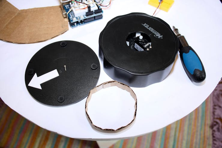
ขั้นตอนที่ 1: สร้างโครงสร้างแท่นกล้องพื้นฐาน
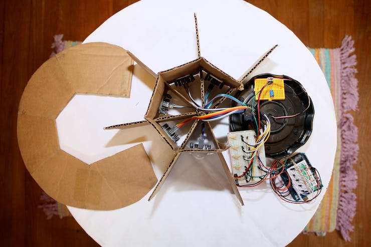
ขั้นตอนที่ 2: ยึดมอเตอร์และสมดุลโครงสร้าง
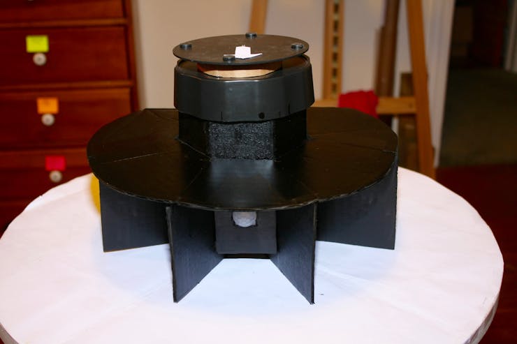
ขั้นตอนที่ 3: ติดกล้องและการทดสอบครั้งสุดท้าย
Schematics
แผนผังการต่อวงจร (Circuit Diagram) แสดงการเชื่อมต่ออุปกรณ์ทั้งหมด:
แผนผังด้านบนแสดงการเชื่อมต่อแบบสมบูรณ์ ระหว่าง Arduino, PIR Sensor, Motor Driver และ DC Motors
Code (Arduino Sketch)
คำสั่งโปรแกรม Arduino (Sketch) ที่ควบคุมระบบ Motion Following:
 // Motion Following Motorized Camera Base

       // Arduino Sketch by Lindsi


       // Define pins

       #define PIR_PIN 2 // PIR Sensor pin

       #define MOTOR_IN1 8 // Motor Driver IN1

       #define MOTOR_IN2 9 // Motor Driver IN2

       #define MOTOR_IN3 10 // Motor Driver IN3

       #define MOTOR_IN4 11 // Motor Driver IN4


       // Sensor reading variables

       int sensorValue = 0;

       int previousValue = 0;

       int detectionCounter = 0;


       void setup() {

         Serial.begin(9600);

         pinMode(PIR_PIN, INPUT);

         pinMode(MOTOR_IN1, OUTPUT);

         pinMode(MOTOR_IN2, OUTPUT);

         pinMode(MOTOR_IN3, OUTPUT);

         pinMode(MOTOR_IN4, OUTPUT);


         // Initial stop

         stopMotors();


         Serial.println("Motion Following Camera Base Ready!");

       }


       void loop() {

         sensorValue = digitalRead(PIR_PIN);


         if (sensorValue == HIGH) {

           detectionCounter++;

           Serial.println("Motion detected!");


           // Start motors

           moveForward();

           delay(500);


           // Pan motor

           rotatePan();

           delay(300);


           // Tilt motor

           rotateTilt();

           delay(300);


           // Stop

           stopMotors();

         } else {

           stopMotors();

         }


         previousValue = sensorValue;

         delay(100);

       }


       void moveForward() {

         digitalWrite(MOTOR_IN1, HIGH);

         digitalWrite(MOTOR_IN2, LOW);

         digitalWrite(MOTOR_IN3, HIGH);

         digitalWrite(MOTOR_IN4, LOW);

       }


       void rotatePan() {

         // Pan motor rotation (left-right)

         digitalWrite(MOTOR_IN1, HIGH);

         digitalWrite(MOTOR_IN2, LOW);

       }


       void rotateTilt() {

         // Tilt motor rotation (up-down)

         digitalWrite(MOTOR_IN3, HIGH);

         digitalWrite(MOTOR_IN4, LOW);

       }


       void stopMotors() {

         digitalWrite(MOTOR_IN1, LOW);

         digitalWrite(MOTOR_IN2, LOW);

         digitalWrite(MOTOR_IN3, LOW);

         digitalWrite(MOTOR_IN4, LOW);

       }
สำคัญ: ปรับแต่ง delay() values และตรรมชาติการหมุน (Forward/Backward) ตามลักษณะแท่นกล้องของคุณ
Credits & References
-
Project Creator: Lindsi8784 (Hackster.io)
-
Arduino Community: Arduino.cc - Open-source hardware & software
-
Documentation: Arduino Official Library Docs
-
Hardware Resources: Adafruit, SparkFun Electronics
บทความเขียนโดย: Globalbyteshop Team
วัตถุประสงค์: แนะนำโปรเจกต์ Arduino Motion Following Camera Base สำหรับ Makers, Content Creators และผู้เรียนรู้ที่สนใจงานอิเล็กทรอนิกส์
ที่มา: Hackster.io | Arduino Community | DIY Electronics
ภาษา: ไทย (Translated & Adapted for Thai Audience)


